Green Energy Earthing Installations
- Oct 25, 2023
- 2 min read
Updated: Jan 12

Why is Electrical Earthing important?
The cost effective planning and installation of new solar and wind farms and their associated electrical grid infrastructure, requires a full understanding of a site’s electrical properties in order to design an appropriate earthing system, which may include earthing plates, earthing rods, or earthing pits, depending upon the exact requirements and site conditions. If not earthed correctly, solar panels and other electrical equipment can be damaged by electrical surges, lightning strikes, and other electrical disturbances. Such damage can then reduce the efficiency of the solar panels or wind turbines, and even cause them to fail completely, leading to costly repairs or replacements and impacting operational efficiency.
Soil Resistivity Testing
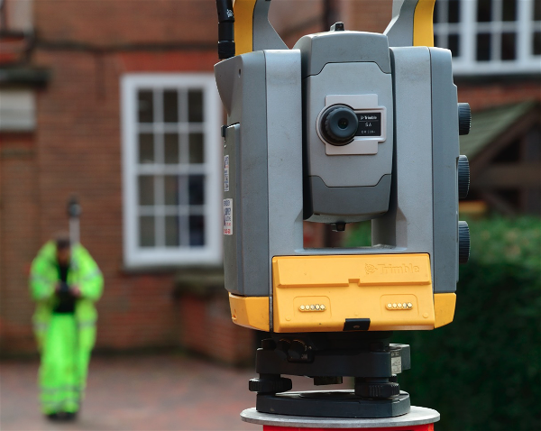
Soil resistivity measures the capacity of the ground to pass an electrical current and is a critical factor in the planning and installation of a suitable electrical earth, with soil layer models forming the basis of such grounding designs. The models are produced from accurate soil resistivity testing carried out on site at the predevelopment stage. Standard soil resistivity testing involves four electrodes set-out in a fixed configuration array. A low frequency electrical current is applied across the two outer current electrodes and the resistance then measured between the two inner potential electrodes.

Above – Soil resistivity testing in progress on a new solar farm development.
A series of depth readings are acquired using different electrode spacings, allowing the apparent resistivity of the ground to be recorded at regular depths to 50m or more at any given point. The resultant data are presented in tabulated form (below) as well as in graphs, listing the electrode spacing; nominal testing depth; electrical resistance for each electrode spacing (R1, R2); average resistance (Rav) and apparent resistivity for each position. As a general rule, lower resistivities make the design and installation of an earthing system simpler.

Above – Tabulated soil resistivity testing results at standard electrode spacings.
The resistivity values are also correlated with borehole data from the site to provide the design engineer with an electrical model of the soil and bedrock layering that can also be correlated with borehole data from the site. A typical model below displays a progressive increase in resistivity with depth.

SUMO can normally mobilise a survey team to match your timing needs. So, why not contact SUMO, before commencing the design of your next solar or wind farm project and thereby maximise the operational efficiency of your design and protect your valuable assets?
Want to learn more?
Please pick up the phone and speak to Dr Marek Wajzer on